Primary Supplies
- Digital calipers
- Scraper
- Material
- RFID material tag
- 3 mm Allen wrench
- Post-processing materials
- Home Position Calibration Cubes.stl
- Home Position Calibration Worksheet.pdf
Get Started
To check, modify, or fine-tune the printer’s parallelism and home position, a Home Position Calibration Cubes.stl file is printed. The printer must be powered on for the duration of the parallelism calibration, and the home position calibration.
Failure to do so can result in material dripping down into or onto the printer causing failed builds and damaged equipment!
Process Calibration .STL File
1. Download the Home Position Calibration Cubes.stl file to the computer where the Live Build DLP software is installed.
2. Open Live Build DLP software and select a buildstyle. See Upload Buildstyle File.
3. Import the .stl file into the Live Build DLP software.
4. Print the Home Position Calibration Cubes.stl.
5. Once the print is completed, check if all nine cubes are on the build platform.
6. If any of the cubes are missing, tap the Manual Debris Removal icon and remove any cured particles that settled to the bottom of the material tray.
Post-Process
1. Gently remove the calibration blocks from the build platform using the scraper.
2. Clean the models.
3. Look closely at each printed block. There is a small number printed on each cube.
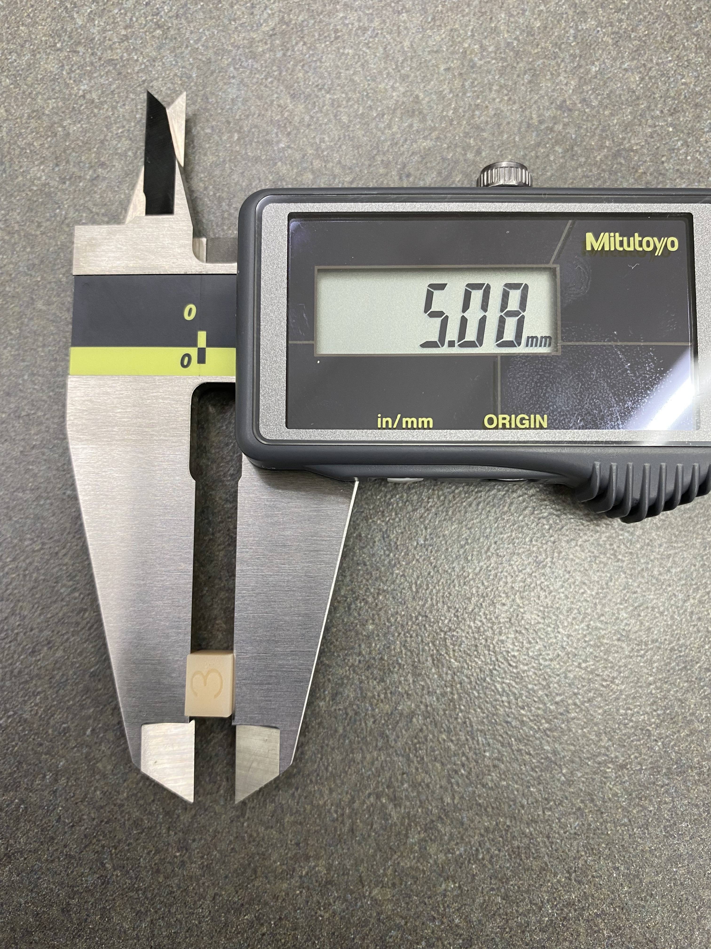
Measure
Measure the height of each cube and write down the values.
- If all the blocks are within +/- 100 microns, then the printer is paralleled, and no further action is required.
- If all the blocks are within 4.90 and 5.10 mm (for the disposable tray: within 4.80 and 4.95 mm), then the printer’s home position is correct, and no further action is required.
If the home position is correct and the printer is not paralleled, then continue to section Adjust Parallelism.
If the printer is paralleled and the home position is not correct, then skip to section Adjust Home Position.
Adjust Parallelism
1. Reference the values from section Measure to determine which side needs adjustment. Find the two extremes. One corner is most likely the highest and the opposite is the lowest. Adjust the higher number to make it lower.
To increase the height measurement:
-
-
- Turn the outer screws, or Set Screws, counter-clockwise (e. g. ¼ turn= 100 microns).
- Turn the inner screws, or Driving Bolts, clockwise (e. g. ¼ turn = 100 microns).
-
To decrease the height measurement:
-
-
- Turn the inner screws, or Driving Bolts, counter-clockwise (e. g. ¼ turn= 100 microns).
- Turn the outer screws, or Set Screws, clockwise (e. g. ¼ turn = 100 microns).
-
2. Find the difference between the two extremes and divide that number in half. This is the adjustment amount.
3. Using the 3 mm Allen wrench, apply adjustments cautiously and precisely.
4. Print the Home Position Calibration Cubes.stl file again and measure the cubes. Adjust the parallelism again as needed.
Adjust Home Position
1. Remove the platform from the printer and place it aside on a clean work surface.
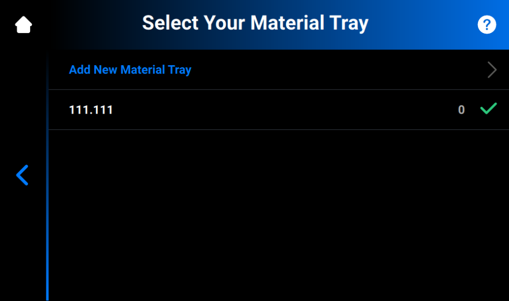
2. Press Settings > Move & Calibration > Home Calibration in Envision One Control Software.
→ The following screen appears with a list of material trays. The material trays included in the list have been calibrated and the calibration data is saved. The numbers on the right of the material tray name show the number of prints done for each material tray.
- If you have already calibrated the platform position with this material tray, proceed to Step 3.
- If you want to add a new material tray, proceed to section Add New Material Tray.
3. Find the serial number or name of your material tray in the list and tap it.
→ The warning message appears asking if you are sure you want to recalibrate the existing material tray. Confirm by pressing OK.
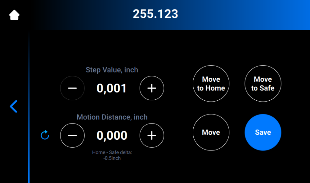
→ The following screen appears.

4. Press Move to Home.
→ The build platform holder moves down the Z-axis to the current home position.
5. Set the value of a step by tapping the–and + icons of Step Value. This is the increment used for the Motion Distance. The Step Value increments can be set to 0.01, 0.10, 1.00, and 10.00.
6. Set the motion distance of the platform by tapping the – and + icons of Motion Distance. This is the total distance the platform moves.
7. Reference the values from section Measure to determine the new home position. The adjustment should be made based on the average height of the calibration blocks.
- If the average height measurement is below 4.90 mm, move the platform up by pressing Move the required number of steps to reach 5.00 mm.
- If the average height measurement is above 5.10 mm move the platform down by pressing Move the required number of steps to reach 5.00 mm.
8. Set the motion distance to the required adjustment. Press Move to make the adjustment. Press Save.
→ The build platform holder starts moving up to the top of the Z-axis.
→ The new home position is set.
Add New Material Tray
To add a new material tray to the list, proceed as follows:
Navigate to Settings > Move & Calibration > Home Calibration > Add New Material Tray.
→ The following screen appears.
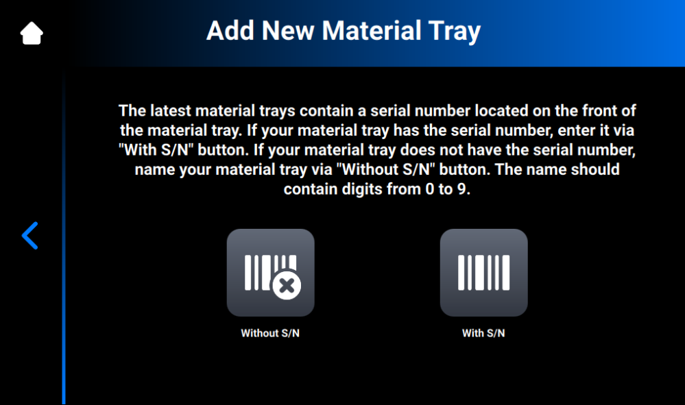
If your material tray has the serial number:
1. Press With S/N.
2. Find the serial number on the front of your material tray and enter it into the field on the screen that appears.
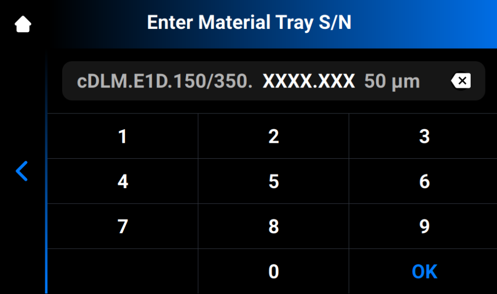
3. Press OK.
→ The following screen appears.
4. Move to the section Adjust Home Position above to complete the calibration.
If your material tray does not have the serial number:
1. Press Without S/N.
2. Name your material tray and enter the name to the field on the screen that appears. The name should contain 7 digits from 0 to 9.
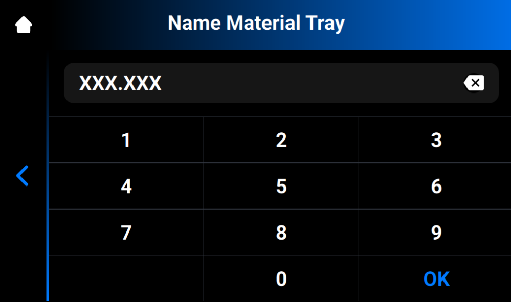
3. Press OK.
→ The following screen appears.
4. Move to step 4 of Adjust Home Position to complete the calibration.